This last year I spent a lot of time on
making the Crumar DS2 "Total Recall". Total Recall means that
what you see on the DS2 is exactly the same as what the values
are in the VST it is controlling. There are almost no
synthesizers which can do this: When you a change a patch on a
synthesizer, the controller just shows the wrong values. This
off course is very annoying and moreover, when you move a slider
or rotate a button you get serious hickups.
As I stated 'I spent a lot of time' to create this option, not
only for the DS2, but for my full DAW system.
This page will go in pretty much detail, because there are many
problems to be tackled. But first some pictures from the outside ☺ and inside ☹:
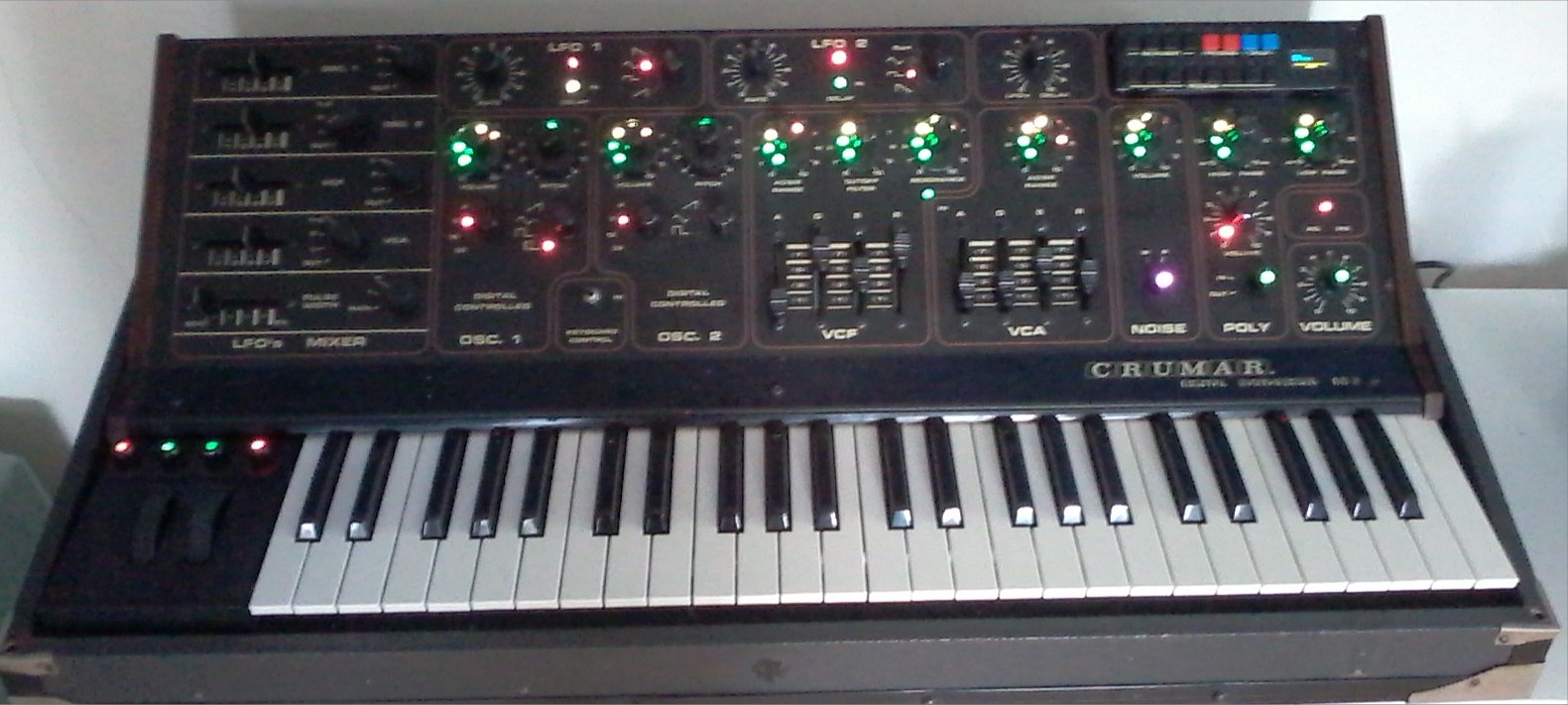
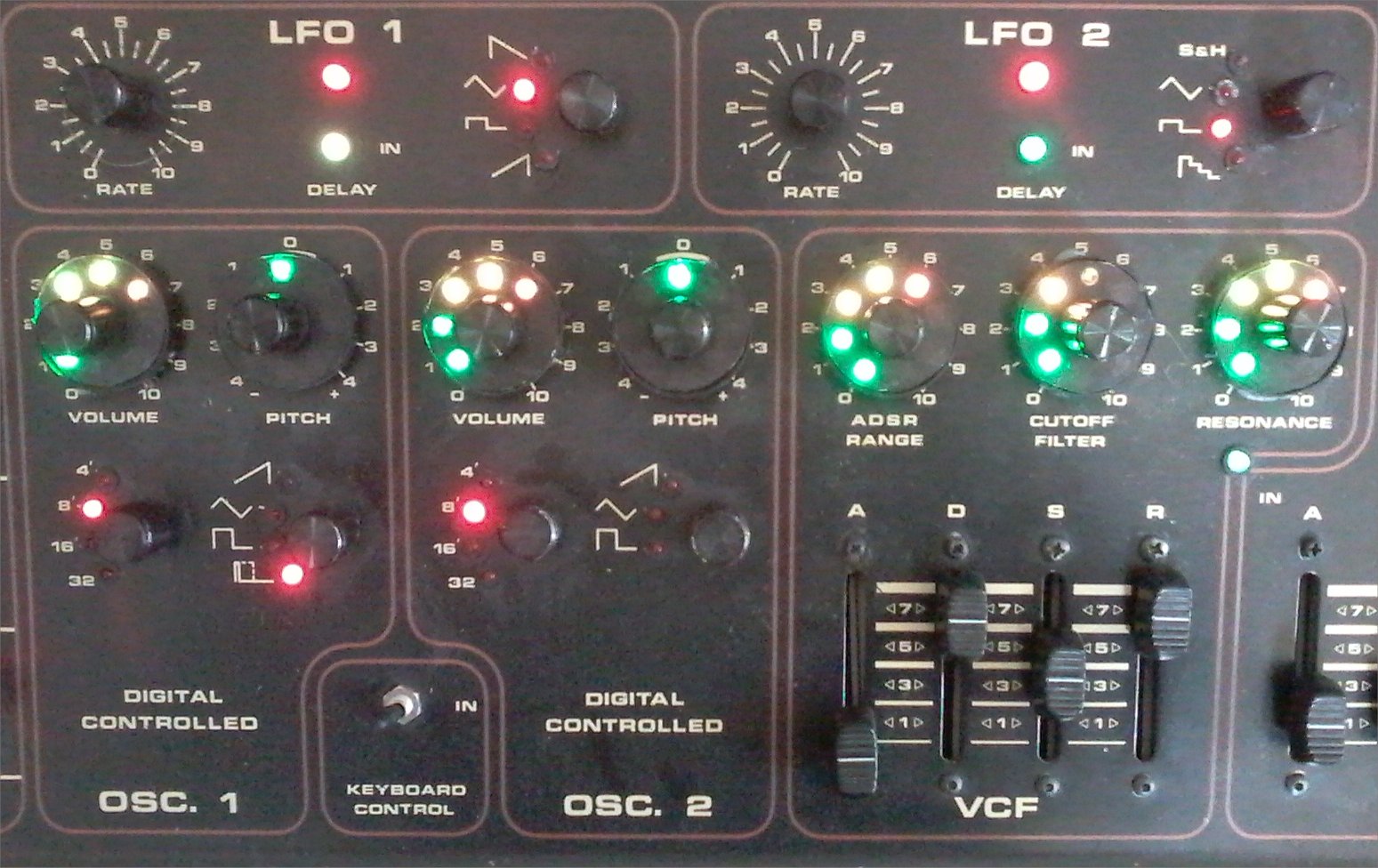
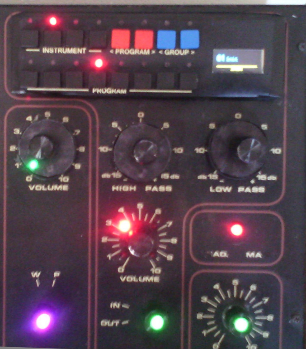
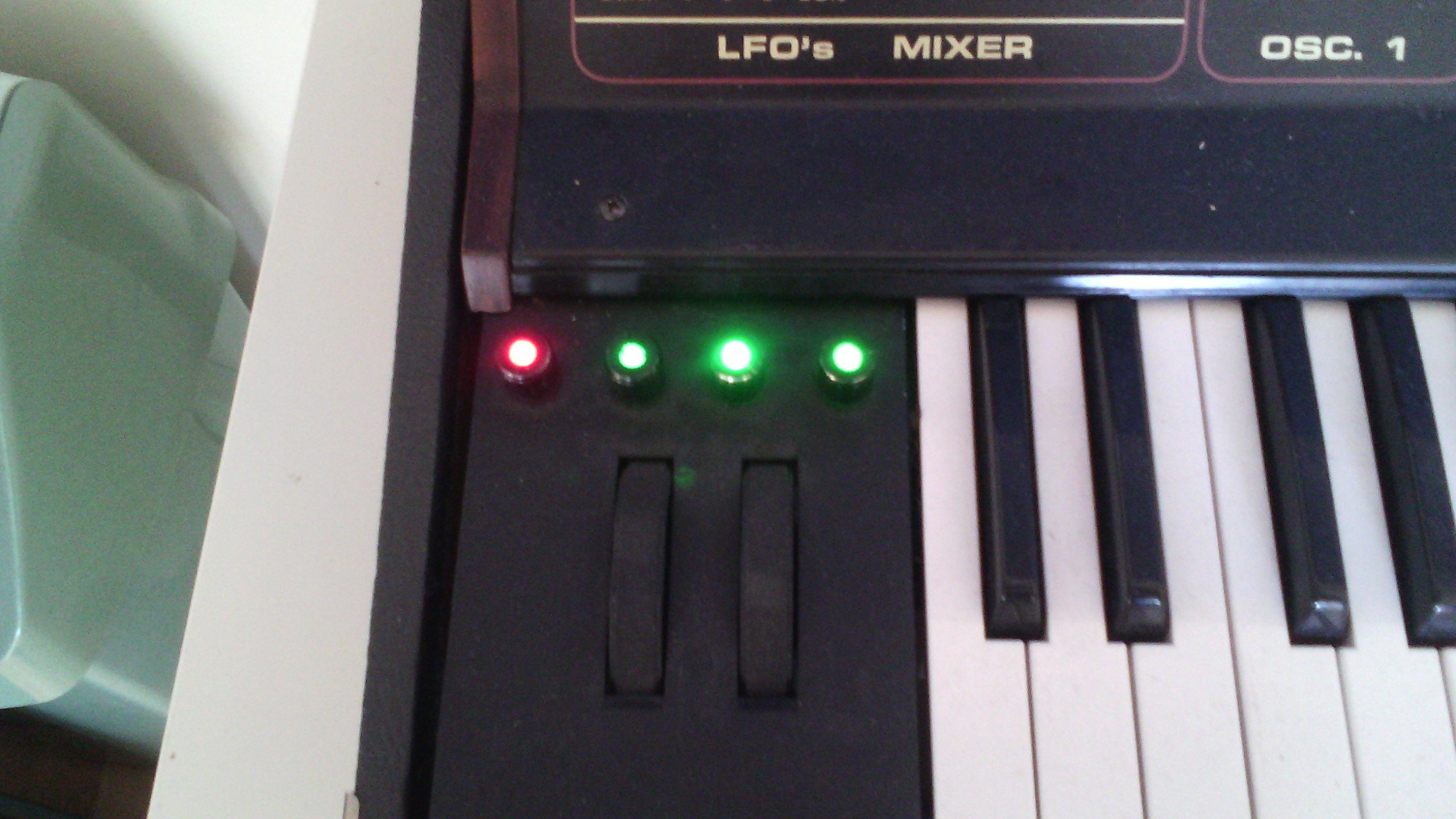
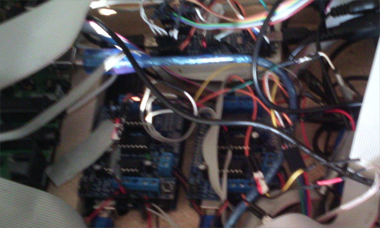
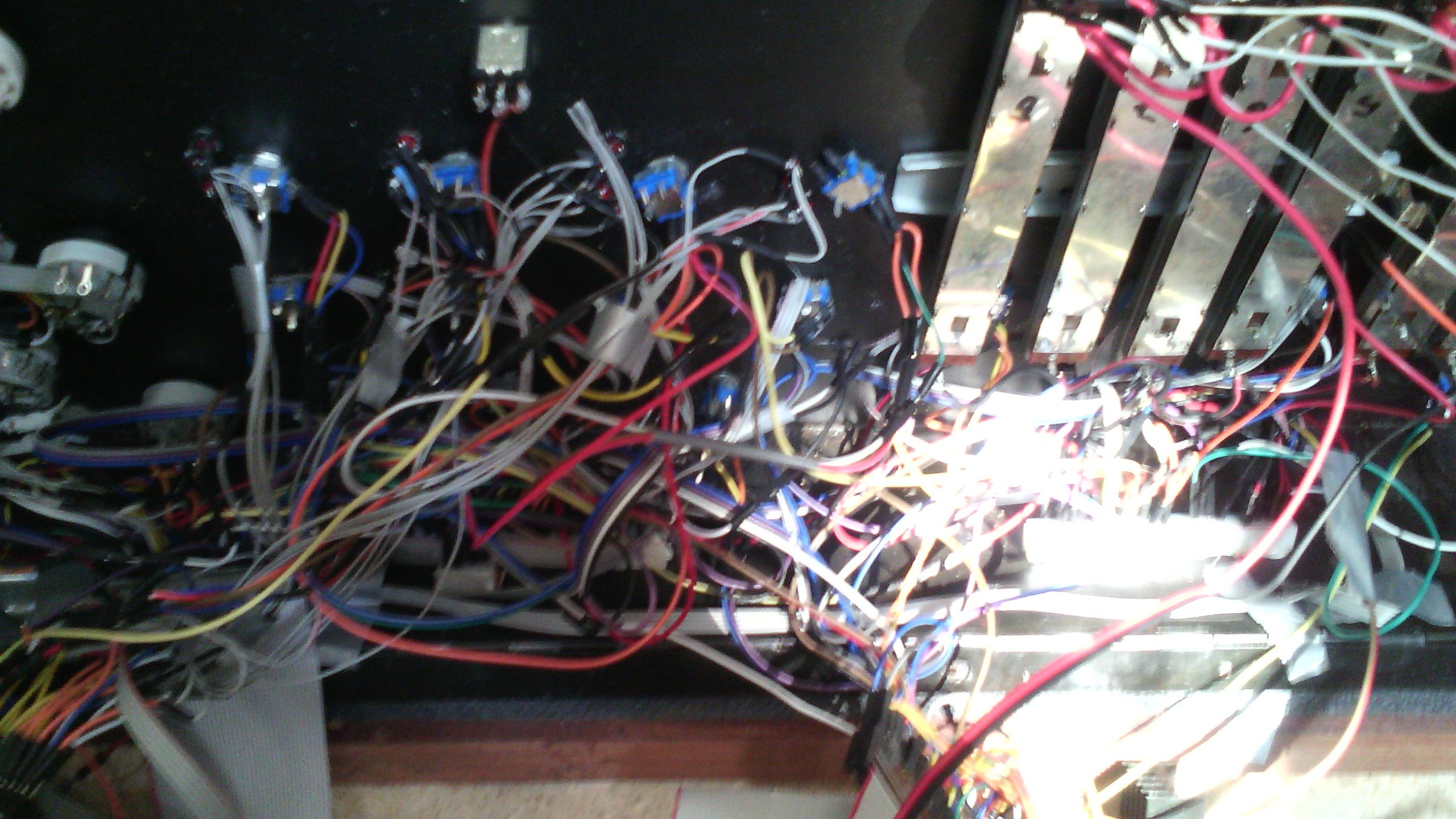
The Crumar was designed as a synthesizer where you fiddle the knobs and then you hear immediate results: Rotate the cutoff controller and you hear your sound brighter. However, there is no visual feedback if a VSTs cutoff is changed, because the rotators don't act that way. Moreover, if you change a patch, nothing happens on the Crumar view.
To make it Total Recall I had to make a view for all controllers. In the picture below you can see the new Crumar with additional visual feedback: Almost all encoders (e.g Volume Oscillators) have a ledring surrounding it, showing the correct position, all selectors (e.g. LFO wave selector, OSC footage) have leds for the chosen position, and both Envelope Generators (VCF ADSR, VCA ADSR) have motorized faders. All encoders and selectors have been replaced with relative encoders: They don't have a minimum or maximum value.
2. Crumar DS2 hardware
Before going on, this is a good place to thank my collegue Paul van Venrooij, who helped a lot with designing, creating, destroying, recreating the hardware needed for this, and other projects!
To achieve the desired functionality, about 200 connections had to be made from embedded hardware to the controllers: Digital I/O's, Led control, Neopixel control, Motor control. On the picture below you can the internals of the Crumar. I had no experience with hardware design, so all connections were monitored in a few Excel sheets and indeed, most connections are wired.
At the moment there are 7 (Arduino) controllers involved to make this system work. They communicate with the hardware over I2C, Serial, SPI, Wireless MIDI, Digital and Analog I/O. Maybe you think that 7 Arduino's is a bit too much and that I should have used something faster, like a Raspberry Pi. However, speed is not the issue, much more the large amount of control lines and the convenient way to split up the functionality over several subboards (including a way to relatively fast switch hardware components (like LCD, Oled, you name it)) made me decide to create this architecture.
There is one Mega Arduino controlling most of the encoders, including a MuxShield with 48 extra I/Os. This is also the Arduino which handles I/O to the MIDI Arduino and additionally controls the 80 Neoleds in the ledrings (this is done with only 1 digital output, thank you Adafruit).
There is one Mega Arduino which handles most of the analog connections (a few sliders plus 6 RGB Leds) and communicates with the Motor Arduino's. It also monitors the encoders on the rotators to the left of the keyboard.
There are two Arduino UNO's controlling the Motor shields, needed for the ADSR faders. The Motorized faders are pretty delicate: They were removed from a Behringer BCF2000. At first the full Behringer controller was used (including two MIDI bridges, with optocouplers and such), but later I opted to use two motorshields instead of this big controller. I chose two Arduinos for control, because power consumption is a big issue here and therefor it is easier to have two simple, stable systems instead of a complex one.
There is one Arduino Nano connected to the OLED and Button Patch Selector. This one works on 3.3Volt, which is needed by the OLED. For the Patch Selector (plus leds) all 20 Lines of the Nano are used, using a matrix construction. Paul van Venrooij created this hardware.
There is one Arduino Pro Micro, which just serves as a Serial to MIDI convertor. I used the LUFA framework here, plus some HIDUINO sources but extended this to edit the Device Name over SysEx control. There's also a connection to a CME WIDI connector but I am not using that now.
The last controller controls the keyboard, the modulation wheels and aftertouch. The keyboard is a standard MIDI keyboard from CME. Many of these keyboards use the same way of interfacing. Although the keyboard was once connected to the Main Arduino, I switched to the original CME Embedded board for this as it gives me a comfortable feel about latency issues and correct velocity sensing and aftertouch. The CME board communicates with the Master Arduino over Serial port.
All these 7 devices can be debugged separately because they are all connected to a 7-ports HUB which communicate with the Host. However, for MIDI view, there is only exactly one device present, named 'Crumar DS2'.
3. Embedded Software
For the Embedded Software I used three essential tools: The Arduino IDE, Visual Studio 2013 and Visual Micro. Most of the time, the early stages of the software are done from within the Arduino IDE, but when things get more complex it is wiser to switch to a better IDE, which supports multiple files, easy class design, code completion etcetera. Visual Studio (with plugin VisualMicro) is used then.
So, the main goal for the Embedded Software is to create an interface from the hardware to the Midibus. You can imagine there is a protocol designed with which you get notified of changes on the Crumar and the other way round, let the Crumar react to changes on the PC (I'll talk about the PC software in the following paragraph). So, the Master Arduino receives and sends command from this protocol, translates them to/from messages for the Hardware classes and calls/get notified the correct code, or passes data to another Arduino. I've created a nice C++ framework for this which you can use in many projects. As stated before, all Arduino's have there individual upload port, so you can change subsystems quite easily. With aid of the framework it is just 'filling in the blanks', that is, fill in the hardware dependent parts.
Since I mostly do the initial stuff in the Arduino IDE and fix issues there, working with a processor which has no debugging facilities is not too much of a burden.
4. PC Software
To create a full system which is total recall, it off course is needed to create a framework where you can add controllers, views, (bi-directional) connections to the DAW. This is my other project: Virtual Controller based MIDI system. For details on the virtual Controller framework and the connection to DAWs see that page. For the Crumar interface, all what is needed now is software which maps the MIDI control data to the Virtual Controller Framework. To give an indication: In the Virtual Controller Framework there is a controller named Oscillator1 Wave, which can have eight different waveforms. When changing a Waveform on the Crumar a protocol message (BTW, all are send as Midi SysEx messages using the RMS protocol) is sent which is converted to a Virtual Controller Message from within a mapping class. Care must be taken to map to the correct wave!
Alternatively, when changing a controller in a VST (or selecting another patch), the Surface controller in the DAW will generate a message, which will be converted to the Virtual Controller Framework and after that will be translated into a SysEx message for the Crumar MIDIPort. This all sounds simple, and in fact it is, but there's a lot of bookkeeping to do!
